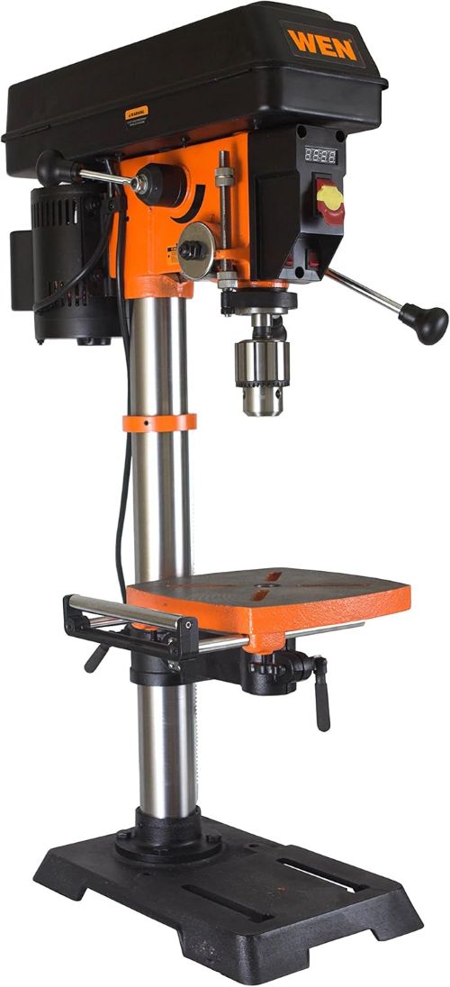
You troubleshoot this drill press by isolating mechanical belt slippage from electrical sensor faults. Next, inspect the variable speed Reeves pulley assembly while running the motor. Check the JT33 chuck arbor runout with a dial indicator to eliminate drilling wobble.
Workshop surveys reveal that eighty percent of benchtop drilling errors stem from loose arbor tapers. Furthermore, a tuned Wen DP1263V benchtop drill press maintains runout under five thousandths of an inch. In fact, regular diagnostic checks prevent sudden motor stalls and preserve workshop drilling precision. Therefore, this comprehensive guide provides proven repair solutions for every common mechanical failure.
Key Takeaways
- Always adjust the mechanical variable speed lever while the induction motor runs continuously.
- Clean the optical tachometer sensor disc to eliminate erratic digital LED speed readings.
- Wipe the JT33 chuck arbor taper thoroughly with solvent before reseating the spindle chuck.
- Tighten the quill spring housing counterclockwise to restore crisp automatic handle retraction.
- Realign dual laser diode set screws using a crosshair square on scrap lumber.
- Inspect the Reeves drive belt tension to prevent sudden stalling during heavy drilling operations.
Diagnosing Mechanical Variable Speed and Reeves Drive Problems
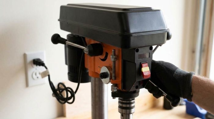
Correcting Reeves Drive Pulley Jamming and Speed Freezes
The Wen DP1263V utilizes a split-sheave mechanical Reeves drive to adjust rotational speed smoothly. Specifically, this mechanism alters pulley diameter between 530 and 3,100 revolutions per minute. Never force the variable speed control handle while the motor rests stationary.
Forcing the lever without motor rotation bends the internal cast aluminum linkage arms quickly. Consequently, the mobile pulley halves bind on the central splined drive shaft. Apply two drops of synthetic dry PTFE lubricant to the center sliding hub regularly.
Wood resin and fine sawdust often form sticky buildup inside the moving pulley sheaves. In fact, packed debris prevents the moveable sheave from sliding smoothly across the shaft. Blow compressed air through the top belt housing to dislodge packed wood particles immediately.
Replacing and Tensioning the Variable Speed Drive Belt
Worn drive belts slip under drilling resistance and cause severe spindle chatter during deep cuts. First, disconnect electrical power by pulling the three-prong plug from your workshop outlet. Open the hinged top steel pulley cover to examine the rubber drive belt surface.
Look closely for glazed sidewalls, missing drive teeth, fraying cords, or rubber dry rot. Next, shift the speed control lever toward high speed to open the front pulley. Roll the old belt carefully off the rear motor pulley sheave by hand.
Install an authentic OEM replacement belt over the front spindle pulley assembly first. Then, rotate the rear pulley manually while rolling the rubber belt into position. Adjust the rear motor mount tension bolt until the belt deflects one-half inch under thumb pressure.
Calibrating the Digital LED Speed Display and Tachometer
Cleaning and Aligning the Optical RPM Sensor
The front digital LED display reports accurate spindle speed in real time during drilling tasks. However, airborne dust particles frequently cover the internal optical tachometer pickup sensor. A blinded optical sensor causes the digital screen to flash blank or display zero RPM.
Locate the infrared pickup sensor mounted beside the slotted spindle disc under the cover. First, wipe both sensor lenses gently using an isopropyl alcohol cotton swab. Additionally, inspect the rotating slotted encoder wheel for bent teeth or sticky pitch deposits.
Straighten any warped encoder disc tabs carefully with needle-nose pliers to ensure uniform clearance. Maintain an exact gap of two millimeters between the optical sensor and passing tabs. Spin the spindle assembly manually to verify that rotating tabs never strike the sensor body.
Eliminating Digital Readout Flickering and Speed Discrepancies
Erratic digital numbers that jump wildly indicate loose electrical wiring or electromagnetic interference. Furthermore, vibration from out-of-balance pulleys often shakes wire harness connectors loose over time. Trace the two-conductor sensor cable leading from the spindle housing into the digital module.
Press the plastic terminal plug firmly into the digital display circuit board socket. Next, secure loose sensor wiring against the cast iron headstock using nylon zip ties. Proper cable routing isolates sensitive tachometer signals from motor electromagnetic interference effectively.
Test the speed display by running the drill press across its full operating spectrum. Verify that the digital numbers climb smoothly from 530 up to 3,100 RPM. Steady digital readouts confirm proper sensor alignment and reliable electronic signal transmission.
Correcting Chuck Wobble and Spindle Runout
Inspecting the Morse Taper MT2 Spindle and JT33 Chuck Arbor
Excessive chuck runout ruins woodworking joinery and breaks fragile carbide metal drill bits quickly. In fact, drill bit wobble usually originates from an unseated Jacob’s Taper 33 arbor. You must isolate spindle runout from chuck runout using a precision dial test indicator.
First, clamp your magnetic indicator base firmly onto the heavy cast iron work table. Rest the sensitive indicator stylus against the internal ground taper of the empty spindle. Rotate the spindle pulley slowly by hand while reading the dial indicator needle sweep.
A healthy Wen DP1263V internal spindle taper shows less than one-thousandth of an inch deviation. If spindle runout exceeds two thousandths, replace the internal quill ball bearings immediately. Otherwise, focus your repair efforts on cleaning and reseating the JT33 arbor chuck assembly.
Reseating the JT33 Chuck for Sub-Mil Runout Accuracy
Lower the quill assembly completely to expose the central arbor knock-out drift key slot. Drive the tapered steel drift key into the slot using a brass workshop hammer. Catch the falling chuck and arbor carefully with a folded shop towel beneath.
Mineral oils, shipping grease, and wood shavings prevent perfect mating between internal tapered surfaces. Clean the MT2 arbor shank and JT33 chuck socket using quick-drying acetone solvent. Dry both matching metal tapers completely with clean, lint-free microfiber shop cloths.
Next, open the chuck jaws fully until they retract into the steel chuck body. Push the arbor and chuck firmly upward into the female spindle taper by hand. Seat the taper permanently by striking a scrap hardwood block against the chuck base.
Realigning Precision Laser Crosshairs and Depth Stop
Adjusting the Dual X-Y Laser Diodes
The onboard Class II laser system projects red intersecting lines onto your workpiece surface. However, prolonged drilling vibration shifts the delicate laser diodes out of factory alignment over time. Misaligned lasers lead to inaccurate hole placement and ruined custom woodworking components.
First, insert a sharp brad-point bit into the 5/8-inch keyed drill chuck securely. Lower the quill to make a tiny center indentation in a flat scrap board. Raise the quill handle back to its uppermost resting position without moving the board.
Switch on the laser power toggle switch on the front control panel. Next, loosen the hex set screws securing each laser diode in the headstock casting. Rotate and pivot each diode barrel until the red crosshairs intersect over your center indentation. Snug the locking set screws gently to secure the laser diodes without cracking their housings.
Calibrating the Quill Depth Stop Collar
Repeatable hole depth relies on an accurate threaded depth stop rod and knurled thumb nuts. Woodworkers frequently encounter depth creeping when locking nuts loosen during aggressive repetitive drilling cycles. Always clean wood chips and abrasive dust from the threaded depth rod regularly.
Furthermore, verify that the pointer needle aligns accurately with the cast metric and imperial scale. Lower your drill bit until the cutting tip touches your workpiece surface lightly. Zero the indicator scale and tighten both knurled jam nuts firmly against each other.
Tensioning the Quill Return Spring for Smooth Travel
Adjusting the Spring Housing and Locknut Assembly
The quill return spring automatically lifts the spindle chuck after completing each drilling stroke. However, repeated cycling weakens spring tension and causes the feed handle to sag downward. You can calibrate the return spring tension using the external left-side circular housing.
First, clamp the spindle securely in its top position to prevent unexpected rotation. Loosen the outer locknut while holding the circular spring housing firmly with channel-lock pliers. Never let go of the housing because the internal coiled spring stores significant tension.
Pull the housing outward slightly to clear the alignment boss pins on the casting. Next, rotate the housing counterclockwise one-quarter turn to increase return lifting force. Push the housing inward over the pins and tighten the outer locknut securely.
Preventing Quill Play and Spindle Slop
Excessive side-to-side quill play allows drill bits to wander off target in hardwoods. Specifically, wear between the steel quill body and cast headstock causes loose mechanical tolerances. Locate the quill adjustment bolt positioned on the right side of the main casting.
Loosen the exterior locking nut using a metric box wrench. Turn the center socket set screw clockwise until you feel light contact against the quill. Then, back the set screw out one-eighth turn to prevent binding the feed mechanism.
Tighten the locknut securely while holding the adjustment screw in place with an Allen wrench. Move the quill feed handle up and down to check for silky, unhindered motion. This calibration eliminates lateral slop while preserving effortless quill return travel across all jobs.
Resolving Motor Humming, Stalling, and Electrical Faults
Testing the 5-Amp Motor Start Capacitor
An induction motor that hums loudly without spinning signals a damaged start capacitor. In addition, defective centrifugal starting switches prevent the motor from reaching full operational speed. Always disconnect power before touching any motor wiring or opening metal capacitor covers.
Remove the curved metal cover on the side of the 5.0-amp motor housing. Discharge the cylindrical capacitor safely using an insulated screwdriver across both electrical terminals. Test microfarad capacitance using a digital multimeter set to the capacitance testing mode.
Compare your multimeter reading against the microfarad rating printed on the capacitor label. Consequently, replace any capacitor that exhibits bulging ends, oily leaks, or weak microfarad readings. Install a factory-certified replacement capacitor to restore instant motor startup torque reliably.
Inspecting the Safety Power Switch and Thermal Overload
Heavy drilling loads heat motor copper windings and trigger internal thermal overload cutoffs. Allow the warm motor to cool down for thirty minutes before attempting a restart. Press the small red reset button on the motor casing if equipped.
Furthermore, inspect the front paddle power switch for loose wire connections or broken rocker tabs. Remove the yellow safety lockout key and check its contacts for physical wear or oxidation. Clean dusty switch terminals using non-conductive electrical contact cleaner spray.
Wen DP1263V Diagnostic Troubleshooting and Mechanical Symptom Matrix
Systematic diagnosis saves valuable workshop hours and prevents unnecessary replacement of functional parts. For example, matching mechanical noises with specific mechanical assemblies identifies root causes quickly. The following matrix outlines common operational symptoms alongside proven workshop repair actions.
| Operational Symptom | Probable Root Cause | Diagnostic Check | Proven Repair Action |
|---|---|---|---|
| Variable speed lever binds or will not move | Speed adjustment attempted with motor stationary | Inspect Reeves pulley linkage arms for bends | Only shift speed lever while motor runs continuously |
| Spindle stalls under moderate drilling feed pressure | Glazed, loose, or oil-contaminated drive belt | Check belt tension and measure center deflection | Tension belt or install fresh OEM replacement belt |
| Digital LED screen flashes zero or blank | Dust covering optical tachometer pickup sensor | Examine encoder disc gap and optical sensor lens | Clean sensor with alcohol and set two-millimeter gap |
| Drill bit exhibits noticeable runout and wobble | Dirty or improperly seated JT33 chuck arbor | Measure taper runout using magnetic dial indicator | Clean matching tapers with acetone and reseat firmly |
| Dual laser crosshairs miss target center point | Vibration shifted diode alignment set screws | Project red crosshairs onto scrap center prick punch | Adjust diode set screws until laser crosshairs align |
| Quill feed handle fails to retract automatically | Weak or loose coil return spring tension | Test return handle rotation across full stroke range | Rotate spring housing counterclockwise and tighten locknut |
| Motor hums loudly but spindle fails to spin | Defective start capacitor or open centrifugal switch | Test microfarads using digital multimeter tester | Replace faulty motor capacitor with rated OEM part |
| Excessive side play in quill during travel | Loose headstock quill guide adjustment screw | Grasp chuck and check lateral mechanical deflection | Snug right-side set screw and secure locknut tightly |
Comparing dial indicator measurements against factory benchmarks pinpoints hidden mechanical wear accurately. In addition, periodic bolt checks ensure that structural vibrations never degrade machining precision over time. Order authentic Wen replacement components to guarantee proper fitment and long-term mechanical reliability.
Preventive Maintenance and Lubrication Routine
Cleaning and Protecting Cast Iron Surfaces
Bare cast iron tables rust quickly in humid garage and basement workshops. Therefore, apply high-quality paste wax to the table top and base casting monthly. Buff the dried wax coating with a clean rag to create a slick, rust-resistant barrier.
Furthermore, avoid water-based metal cleaners because moisture accelerates oxidation inside unpainted casting pores. Use mineral spirits to wipe away sticky sap and cutting oil residue after heavy drilling. Clean table surfaces promote smooth workpiece positioning and accurate 90-degree hole alignment consistently.
Lubricating Mechanical Splines and Column Racks
The vertical steel column and rack-and-pinion elevation gear require regular lubrication. First, brush away trapped wood shavings from the geared rack teeth using a stiff nylon brush. Apply dry molybdenum or PTFE lubricant spray along the gear teeth evenly.
Avoid sticky motor oils and grease on the column because they attract abrasive wood sawdust. In contrast, dry lubricants provide slick table height adjustments without accumulating gritty shop grime. Crank the table elevation handle across its full travel range to distribute lubricant across all teeth.
Extend the quill downward to access the splined spindle drive shaft under the top cover. Next, apply three drops of light synthetic machine oil to the splines twice yearly. Smooth splines prevent chatter and ensure effortless vertical travel through tough hardwoods.
Conclusion: Restore Factory Precision to Your Workshop
Routine troubleshooting keeps your benchtop drill press operating with reliable shop precision for decades. Specifically, clearing dust from tachometer sensors, reseating chucks, and tuning belt tension eliminates common drilling headaches. Regular mechanical adjustments safeguard your valuable woodworking workpieces against costly drilling mistakes.
In fact, simple diagnostic maintenance restores smooth operation and factory-grade hole drilling accuracy quickly. Inspect your Reeves drive pulley and check spindle runout in your shop today. Put these proven repair methods to work and enjoy flawless drilling performance on your next project!
Frequently Asked Questions
Why does my Wen DP1263V drill press vibrate excessively?
Excessive vibration usually stems from a glazed drive belt or an improperly seated JT33 chuck arbor.
Can I adjust the variable speed lever when the motor is off?
No, you must only move the variable speed control lever while the motor runs continuously.
Why is the digital LED speed readout flashing zero RPM?
Sawdust blocks the optical tachometer pickup sensor mounted beneath the top pulley drive cover.
How do I tighten the quill return spring on this drill press?
Loosen the outer locknut and rotate the left-side spring housing counterclockwise by one-quarter turn.
What size chuck and arbor taper does the Wen DP1263V use?
This drill press utilizes a 5/8-inch keyed chuck mounted on a standard Morse Taper MT2-JT33 arbor.