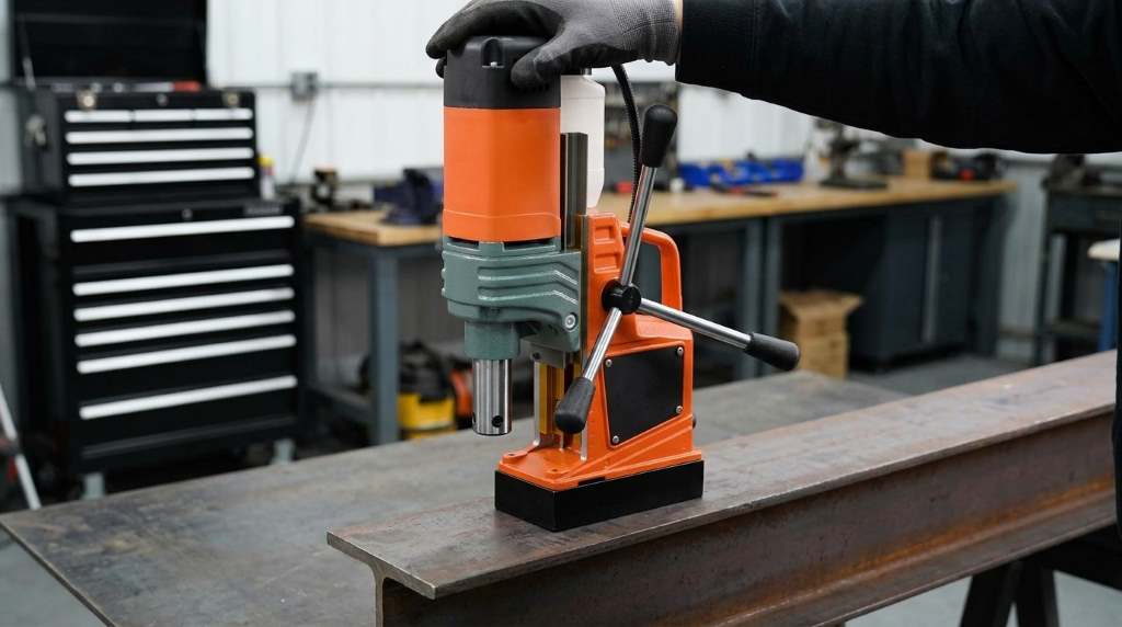
You operate this magnetic drill by securing its electromagnetic base onto clean structural steel. Next, center the pilot pin over your punch mark and switch on the magnet. Turn on the gravity coolant valve and engage the 1450W motor at steady downward pressure.
Heavy steel fabrication demands massive clamping stability and high cutting precision on every job. The Vevor 1450W mag drill press delivers 12,500 Newtons of magnetic holding force. In fact, field tests show annular cutters drill holes up to four times faster than twist bits. Consequently, this comprehensive guide explains step-by-step setup, safe operation, and maintenance practices.
Key Takeaways
- Clean workpiece surfaces thoroughly to maximize electromagnetic grip on structural steel.
- Fasten the safety ratchet strap securely whenever you drill horizontally or overhead.
- Verify that your steel plate measures at least ten millimeters in thickness.
- Align both flat surfaces on the Weldon shank with the spindle grub screws.
- Open the coolant bottle petcock before the cutter touches the metal surface.
- Maintain uniform downward feed pressure to produce smooth, coiled metal chips.
Understanding Electromagnetic Base Adhesion and Steel Thickness
Activating the 12,500 N Magnetic Base
The Vevor mag drill relies on an ultra-strong electromagnet for rigid workpiece clamping. Specifically, this dual-coil magnetic base generates 12,500 Newtons of vertical clamping force. This incredible strength keeps your cutter firmly anchored during heavy metal coring tasks.
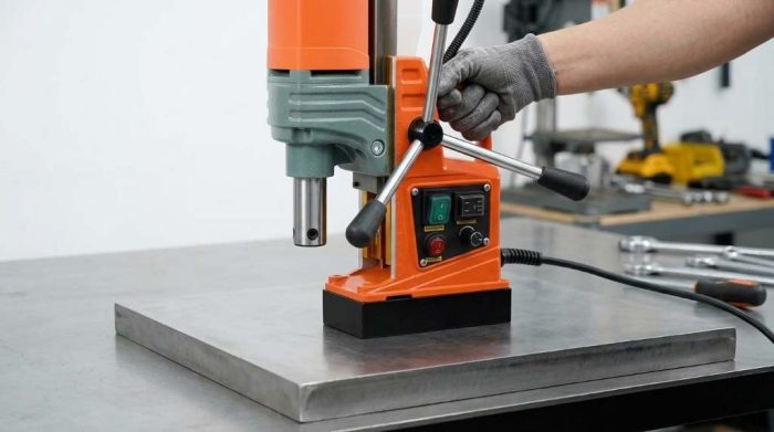
First, wipe away metal shavings, oil film, and rust scale from the target steel area. Even tiny chips create an air gap that degrades magnetic holding power significantly. Next, position the drill flatly against the steel surface without any tilting or rocking. Flip the red magnetic switch on the main control panel to energize the base coil.
Minimum Steel Plate Thickness Requirements
Magnetic flux lines require sufficient steel mass to establish a solid magnetic circuit. Therefore, you need a minimum steel plate thickness of ten millimeters for total adhesion. Thinner steel plates allow magnetic field leakage and reduce clamping force by over fifty percent.
However, fabrication jobs frequently require drilling holes through thin sheet metal or structural tubing. In these situations, clamp a thick steel backing plate beneath your thin work piece. For example, a twelve-millimeter steel backer plate absorbs stray magnetic flux and restores full grip. Additionally, verify firm magnetic lock by tugging the motor housing before starting any cut.
Essential Safety Procedures and Tether Strap Rigging
Securing the Safety Strap for Horizontal and Overhead Drilling
A sudden power interruption instantly de-energizes the magnetic base during operation. Without a mechanical tether, the heavy tool falls and causes catastrophic jobsite injuries. Consequently, safety regulations require an auxiliary tether strap for all horizontal or overhead setups.
First, wrap the included heavy-duty nylon ratchet strap through the drill carry handle. Next, loop the opposite strap end around an overhead structural steel beam or rigid girder. Pull the webbing snug and crank the ratchet handle until you eliminate slack. Furthermore, test the strap tension to verify that the tether supports the full tool weight.
Personal Protective Equipment and Workspace Prep
High-speed annular cutting throws sharp, red-hot steel swarf across your immediate work zone. Therefore, always wear ANSI-approved safety goggles and a full polycarbonate face shield. Heavy leather work gloves protect your hands while handling sharp cutters and ejected slugs.
However, avoid wearing loose gloves near the rotating spindle arbor during active drilling. Snug-fitting attire and sturdy steel-toe boots provide essential operator protection against falling steel slugs. In addition, clear all flammable rags and solvent containers away from the cutting area. Keep a dry chemical fire extinguisher within arm reach throughout your metal fabrication project.
Tooling Setup: Annular Cutters and Weldon Shank Arbor
Installing the Pilot Ejector Pin
Every standard annular cutter operates alongside a hardened central pilot pin. First, slide the slender steel pin into the center hole of the cutter shank. The pointed end protrudes past the cutting teeth to locate your center punch mark accurately.
Additionally, the pilot pin activates internal coolant flow when it retracts under upward cutting pressure. As the cutter penetrates steel, the pin pushes an internal spring-loaded valve open inside the arbor. Finally, the compressed spring drives the pin downward at breakthrough to eject the solid slug. Never operate an annular cutter without its matching pilot pin installed inside the bore.
Securing Annular Cutters into the 3/4-Inch Weldon Arbor
The Vevor 1450W drill uses an industry-standard three-quarter-inch Weldon shank spindle arbor. In practice, this sturdy arbor design features two flat machining recesses on opposite sides of the shank. You must align these dual flats with the internal locking grub screws perfectly.
First, raise the drill head upward using the three-spoke rotating feed handle. Insert the cutter shank into the arbor socket until it seats against the internal shoulder. Next, tighten both hex grub screws firmly using the included metric Allen wrench. Tighten each screw alternately to ensure balanced, concentric clamping across both flat shank surfaces.
Using the Twist Drill Chuck Adapter
Fabrication jobs occasionally require drilling small pilot holes under twelve millimeters in diameter. For these smaller tasks, annular cutters prove impractical and costly compared to standard drill bits. Fortunately, the Vevor drill includes a dedicated Jacobs twist drill chuck and adapter shank.
First, secure the threaded chuck adapter into the three-quarter-inch Weldon spindle arbor tightly. Next, insert your standard twist drill bit into the three-jaw chuck opening. Tighten the chuck jaws evenly using the geared chuck key around all three pilot holes. Remember that twist bits require heavier downward feed pressure than hollow annular core cutters.
Coolant Reservoir and Gravity Lubrication System
Mounting the External Coolant Bottle
Friction generates tremendous heat when annular cutting teeth slice through thick structural carbon steel. Without continuous cooling fluid, tool steel softens rapidly and loses its razor-sharp cutting edge. Therefore, Vevor integrates an external gravity-fed coolant reservoir bottle onto the machine slide rail.
First, slide the plastic bottle bracket into the dovetail mounting slot on the drill body. Tighten the knurled thumbscrew by hand to secure the bottle assembly in an upright position. Then, fill the reservoir with water-soluble semi-synthetic cutting fluid diluted to manufacturer specifications. Avoid using straight motor oils, which smoke heavily and provide inadequate cooling during deep cuts.
Operating the Spindle Feed Valve
Connect the flexible polyurethane coolant tube between the bottle outlet and the arbor brass nipple. Push the tube firmly into the quick-connect fitting to create a leak-free fluid seal. Next, rotate the small brass petcock valve on the bottle base to initiate gravity flow.
Gravity forces fluid through the hollow spindle directly into the center of the rotating cutter. Specifically, as the pilot pin depresses against steel, coolant bathes the cutting teeth from within. For overhead or horizontal drilling, replace liquid coolant with specialized high-tack cutting paste or wax. Consequently, liquid coolant simply spills into the electric motor housing during inverted drilling operations.
Magnetic Force and Cutting Speed Guidelines
Selecting appropriate cutting speeds and understanding magnetic adhesion prevents premature tool wear and machine slippage. For example, larger annular cutter diameters demand lower spindle rotational speeds to preserve tooth geometry. Meanwhile, steel thickness dictates the actual magnetic holding force that anchors the drill chassis securely. The following table details recommended operating parameters, steel thickness ratings, and rotational cutting speeds.
| Cutter Diameter / Tool | Steel Plate Thickness | Magnetic Adhesion | Recommended RPM | Optimal Lubrication |
|---|---|---|---|---|
| 12 mm to 18 mm Cutter | 12 mm (1/2 inch) | 100% (12,500 N) | 650 to 750 RPM | Water-soluble cutting emulsion |
| 20 mm to 28 mm Cutter | 10 mm (3/8 inch) | 95% (11,875 N) | 450 to 550 RPM | Gravity-feed flood coolant |
| 30 mm to 40 mm Cutter | 10 mm (3/8 inch) | 95% (11,875 N) | 350 to 450 RPM | Gravity-feed flood coolant |
| 42 mm to 50 mm Cutter | 12 mm (1/2 inch) | 100% (12,500 N) | 250 to 320 RPM | Heavy duty cutting emulsion |
| 10 mm Twist Drill Bit | 6 mm (1/4 inch) + Backer | 70% (8,750 N) | 700 to 800 RPM | Manual cutting fluid spray |
| Overhead / Horizontal Setup | 12 mm (1/2 inch) | 100% (12,500 N) + Strap | Match cutter size | High-adhesion cutting paste |
Thick carbon steel plates above ten millimeters absorb magnetic flux lines without any saturation issues. Consequently, the 1450W electromagnet develops its full 12,500 Newtons of mechanical clamping force. Furthermore, reducing spindle speed on large 50-millimeter cutters prevents thermal degradation along outer cutting edges. Always match feed pressure and drill speed precisely to your chosen annular cutter diameter.
Step-by-Step Operating Guide: Drilling Your First Hole
Positioning and Energizing the Electromagnetic Base
Accurate hole cutting begins with precise workpiece layout and metal surface preparation. First, strike the desired hole center with a sharp steel punch and heavy hammer. The indent gives the spring-loaded pilot pin an unmistakable locating reference point on the plate.
Next, place the Vevor mag drill onto the workpiece with the magnet switch off. Align the protruding pilot pin tip directly inside your center punch mark. Then, flip the electromagnetic base toggle switch to the On position. Rock the machine handle forcefully to verify that the magnetic base resists all movement.
Starting the Motor and Initiating the Cut
First, once you confirm solid magnetic adhesion, turn the coolant petcock to open fluid flow. Next, press the green motor start button on the side control housing. The 1450-watt motor spins up to operational speed with smooth, high-torque power.
Slowly lower the cutter toward the workpiece by rotating the three-handle feed wheel. Touch the revolving teeth lightly against the steel to form an initial circular groove. Then, apply firm, steady downward feed pressure to peel continuous metal ribbon chips. Avoid excessive crowding, which stalls the electric motor and chips delicate tungsten carbide teeth.
Ejecting the Center Slug Safely
Maintain consistent feed force until the annular cutter breaks through the bottom steel face. Specifically, as breakthrough occurs, reduce downward pressure slightly to avoid jarring the rotating cutter teeth. Immediately upon exit, the spring-pressurized pilot pin forcefully ejects the solid center metal slug.
Furthermore, this hot steel slug flies out at notable speed during vertical operations. Always place a catch bucket or protective mat beneath through-holes to capture falling slugs. Press the red motor stop button to halt spindle rotation before raising the carriage. Finally, inspect the finished hole to verify clean, circular tolerances and smooth edge walls.
Troubleshooting Common Operating Issues
Cutter Chattering or Stalling Under Load
Excessive machine vibration or chattering teeth indicates incorrect feed rate or loose gib ways. First, adjust the brass gib screws along the slide rail to eliminate carriage play. Loose slide rails allow the heavy motor head to deflect under upward cutting thrust.
Additionally, dull cutter teeth cause severe motor stalling and produce scorched brown chips. Inspect cutting edges under bright shop lighting for chipped tungsten carbide corners or rounded edges. Replace worn cutters immediately to prevent motor overload and preserve the 1450-watt armature windings. Moreover, increase coolant flow rate to reduce friction and suppress harmonic cutter vibrations.
Slug Jamming Inside the Cutter Bore
Occasionally, the cut metal slug remains trapped inside the hollow annular cutter body. This jamming problem happens when operators release feed pressure prematurely or skip cutting lubrication. As a result, expanding friction heat pinches the steel slug against the internal bore.
Never strike the cutter exterior with a steel hammer to dislodge a jammed slug. Such impacts chip delicate cutter teeth and permanently distort the precision ground tool body. Instead, press the pilot pin gently against a wooden block on your workbench. Alternatively, squirt penetrating oil inside the arbor and let thermal contraction release the stuck slug.
Loss of Magnetic Holding Power
Unexpected loss of magnetic adhesion presents extreme safety risks during high-torque hole drilling operations. In fact, debris accumulation between the steel workpiece and magnetic base accounts for most adhesion drops. Even microscopic paint chips, mill scale, or dust layers reduce magnetic flux transmission drastically.
Furthermore, thermal overload trips internal circuit protection when operators run the electromagnet continuously for hours. If the base feels exceptionally hot, switch off the drill and allow thirty minutes cooling. Check your extension cord gauge to prevent excessive voltage drop under heavy motor loads. Consequently, always connect the Vevor mag drill into a dedicated fifteen-ampere electrical outlet circuit.
Routine Maintenance and Gib Strip Adjustments
Adjusting Dovetail Gib Screws for Zero Backlash
Routine operation gradually loosens the sliding dovetail ways that support the heavy motor carriage. This looseness creates spindle runout and causes premature chipping along annular cutter edges. Fortunately, you can eliminate slide play by adjusting the brass gib strip set screws.
First, loosen the locking jam nuts along the side of the vertical slide column. Next, tighten each brass gib screw incrementally using a small flathead screwdriver. Turn the three-spoke feed handle to check for smooth travel without binding or resistance. Then, tighten the locking jam nuts securely to preserve your precise slide clearance adjustment.
Motor Carbon Brush Inspection and Cleaning
The 1450-watt copper motor utilizes two heavy-duty carbon brushes to deliver continuous electrical current. Over time, friction wears down carbon material and generates conductive carbon dust inside the motor. Therefore, inspect both carbon brushes every one hundred hours of active drilling operation.
First, unscrew the plastic brush caps located on opposite sides of the motor housing. Remove the carbon blocks and measure remaining brush length using a digital vernier caliper. Replace any brush that measures under six millimeters to prevent permanent commutator damage. Finally, blow dry compressed air into the motor housing to clear loose carbon residue.
Conclusion: Precision Magnetic Drilling Made Simple
Mastering the Vevor 1450W mag drill press elevates your metal fabrication productivity and cutting precision. Following proper magnetic base activation, gravity coolant setup, and safety strap rigging guarantees outstanding hole quality. In addition, routine dovetail gib adjustments and brush inspections keep your machine operating like new.
Consequently, never let difficult steel drilling projects slow down your shop schedule or exhaust your budget. Equip your shop with quality annular cutters, engage the magnet, and drill clean holes today!
Frequently Asked Questions
What is the minimum steel thickness for the Vevor mag drill?
You need at least ten millimeters of steel plate thickness for maximum magnetic holding force.
Can I drill overhead or horizontally with this magnetic drill?
Yes, you can drill in any orientation when you anchor the safety ratchet strap securely.
What shank style does the Vevor 1450W spindle arbor accept?
The machine spindle arbor accepts standard three-quarter-inch Weldon shank annular cutters with dual drive flats.
Why did my annular cutter stop cutting and begin smoking?
Dull cutting teeth or closed coolant flow valves cause excessive thermal buildup and heavy smoke.
How do I drill thin steel sheets under ten millimeters safely?
Clamp a thick steel backing plate beneath thin sheet metal to absorb stray magnetic flux.