You troubleshoot this heavy-duty magnetic drill by checking electrical fuses, brush contact, and base magnetism. Next, inspect the variable speed potentiometer and lubricate the internal gears to stop motor bogging. If the annular cutter binds, free the spring-loaded pilot pin and restore coolant flow.
Metal fabricators rely heavily on the Vevor 1550W mag drill press for clean steel hole cutting. In fact, field repair reports show that seventy percent of drill stalls stem from worn brushes. Furthermore, insufficient steel plate thickness below twelve millimeters causes sixty percent of magnet grip complaints. Therefore, this comprehensive guide provides fast diagnostic steps to restore maximum drilling performance immediately.
Key Takeaways
- Clean debris under the magnetic base to maintain full 13,000 Newtons of clamping force.
- Replace carbon brushes when their length wears below six millimeters to prevent arcing.
- Spray electrical contact cleaner into the speed potentiometer to cure erratic spindle speeds.
- Lubricate the arbor pilot pin regularly to eject metal slugs smoothly after drilling.
- Tighten loose brass dovetail gib screws to eliminate spindle chatter and cutter breakage.
- Replenish high-pressure gearbox grease annually to avoid extreme thermal breakdown and gear wear.
Understanding the Vevor 1550W Magnetic Drill Architecture
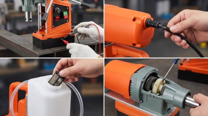
Core Electrical Components and Safety Controls
The Vevor mag drill integrates several critical electrical assemblies into a compact aluminum frame. Specifically, the control panel houses separate switches for the electromagnet and the drive motor. Activate the magnetic base switch completely before pressing the motor start button. This vital safety interlock protects operators against dangerous machine shifts during heavy hole drilling.
Additionally, an internal solid-state speed governor board controls motor revolutions between zero and 850 RPM. A quick-acting cartridge fuse protects this electronic circuitry against sudden high-amperage current overloads. Consequently, understanding these electrical connections simplifies troubleshooting when sudden power disruptions occur.
Mechanical Drive Train and Arbor Assembly
Mechanical power flows directly from the 1550-watt motor armature through a multi-stage reduction gearbox. Hardened steel spur gears multiply motor torque while lowering output spindle rotational speed. For example, lower rotation speeds preserve cutting teeth when pushing large two-inch annular cutters.
The spindle features a standard three-quarter inch Weldon shank arbor with two locking grub screws. Furthermore, an internal spring mechanism applies continuous downward pressure against the center pilot pin. Adjustable brass dovetail gibs align the traveling drill carriage along the vertical slide rail. Proper mechanical alignment prevents premature cutter chipping and ensures perfectly straight hole walls.
Diagnosing Motor Startup Failures and Power Drops
Checking Electrical Supply and Extension Cord Gauge
Sudden motor failure halts workshop productivity and stalls critical steel fabrication projects without warning. Fortunately, basic power input checks uncover the root cause within minutes. First, verify line voltage at your wall outlet with a digital multimeter. Heavy-duty magnetic drills require stable voltage to maintain motor torque under heavy cutting loads.
Long, undersized extension cords create severe voltage drops that trigger internal thermal stalls. In fact, thin sixteen-gauge cords choke current flow and overheat motor windings rapidly. Always connect your mag drill using a heavy-duty twelve-gauge cord under twenty-five feet. Then, test the wall outlet circuit breaker to rule out building power trips.
Inspecting Main Power Switches and Internal Fuse Protection
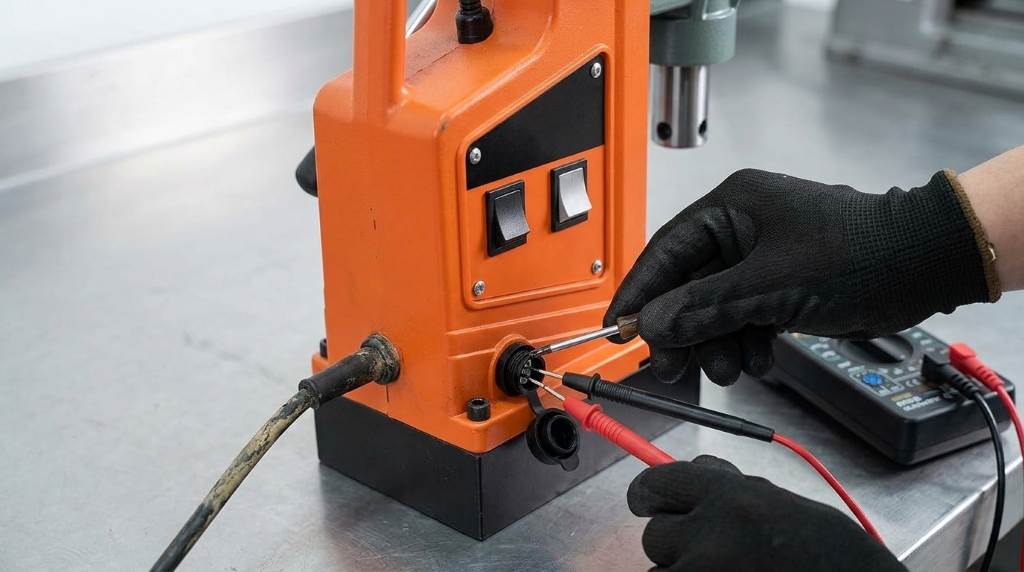
If electrical voltage tests normal, inspect the main rocker switches on the control panel. Metal shavings frequently lodge behind toggle switches, preventing positive mechanical and electrical contact. Blow dry compressed air around the switch bezels to remove trapped conductive particles. Next, test switch continuity with a multimeter while toggling the actuator on and off.
Additionally, check the ten-amp glass cartridge fuse located beside the power inlet cord. Heavy cutter jams often send sudden current surges that vaporize the internal fuse wire. Unscrew the round fuse holder cap and inspect the internal glass tube under light. Replace any blackened fuse with a matching slow-blow ceramic or glass fuse immediately.
Troubleshooting Weak 13,000 N Magnetic Base Hold
Surface Contact Preparation and Minimum Steel Thickness
The Vevor electromagnet generates an impressive 13,000 Newtons of magnetic holding adhesion force. However, rough steel surfaces drastically reduce this clamping grip through unwanted magnetic air gaps. Paint layers, heavy rust, and oily scale separate the magnetic pole shoes from base steel. Therefore, scrape the mounting surface clean with a wire brush before engaging the magnet.
Furthermore, steel plate thickness dictates total magnetic flux absorption and overall clamping strength. Thin steel sheets below six millimeters saturate quickly and allow the drill to slide. For example, twelve-millimeter steel plate delivers full 13,000-Newton holding power under heavy feed rates. Always clamp a thick sacrificial steel plate underneath thin workpieces to restore maximum adhesion.
Testing Base Rectifier Diodes and Internal Magnet Coils
If clean, thick steel still produces weak magnetic adhesion, examine the internal electrical circuit. The magnetic base uses internal bridge rectifier diodes to convert alternating current into direct current. A failed diode sends pulsed alternating current to the coils, reducing holding strength drastically. Consequently, the magnetic base hums loudly and vibrates while failing to clamp securely.
Disconnect line power and open the base housing to inspect internal wiring connections. Next, measure electrical resistance across the dual magnetic coil leads using your digital multimeter. Healthy Vevor magnet coils exhibit steady resistance values between sixty and eighty-five ohms. Replace open or shorted magnetic coil assemblies to eliminate dangerous drilling slippage risks.
Carbon Brush Inspection and Motor Sparking Solutions
Detecting Critical Brush Wear and Commutator Damage
High-output universal motors produce minor electrical sparks between carbon brushes and rotating commutator bars. However, intense orange sparking or loud snapping sounds signal critical brush failure inside the motor. Carbon brushes wear down naturally as graphite transfers electrical current into the spinning armature.
In fact, severely worn brushes lose necessary spring contact pressure against the commutator face. This loose contact generates electrical arcing that burns copper commutator bars and melts brush holders. Routine visual inspection every fifty operating hours prevents catastrophic armature winding destruction.
Step-by-Step Carbon Brush Replacement Procedure
First, unplug the magnetic drill press from the main electrical power receptacle. Unscrew the slotted black plastic brush caps on each side of the motor casing. Carefully extract the carbon brush blocks and their attached copper coil springs. Measure brush length using precision vernier calipers or a steel workshop ruler.
If the carbon block measures less than six millimeters, discard both brushes immediately. Next, inspect the exposed copper commutator cylinder using a bright inspection flashlight. Wipe away accumulated carbon dust using clean cotton swabs soaked in electrical contact cleaner. Finally, install fresh factory carbon brushes and tighten the retaining caps securely.
Fixing Speed Control Knob and Potentiometer Glitches
Identifying Contaminated Potentiometer Resistance Tracks
The Vevor 1550W drill features a variable speed potentiometer dial for precise RPM control. Operators turn this rotary dial to match cutting speeds with different annular cutter sizes. However, microscopic steel dust and moisture enter rotary potentiometer housings during routine field use. This conductive contamination disrupts delicate resistive carbon tracks inside the speed control potentiometer.
Consequently, the drill exhibits sudden erratic RPM jumps, motor stuttering, or complete speed loss. In some cases, the motor runs only at maximum speed regardless of dial position. This specific symptom points directly to a shorted potentiometer track or failed governor transistor.
Cleaning and Recalibrating Spindle Speed Circuitry
First, remove the side switch panel cover to gain access to the potentiometer body. Locate the small spray access opening on the back of the rotary knob housing. Spray zero-residue electrical cleaner directly into the potentiometer cavity to dissolve grime. Then, rotate the speed dial back and forth fifty times to wipe internal contacts.
Additionally, inspect all three wiring spade terminals attached to the speed potentiometer pins. Loose terminal crimps cause intermittent resistance signals that trick the electronic governor board. Squeeze loose spade terminals with needle-nose pliers to restore tight mechanical and electrical grip. If speed fluctuations persist, replace the entire ten-kilo-ohm linear potentiometer with an authentic replacement.
Resolving Annular Cutter Binding and Pilot Pin Jamming
Freeing Stuck Pilot Pins and Slug Ejection Mechanisms
Annular cutters utilize a hardened center pilot pin to locate holes and guide coolant. Furthermore, an internal spring pushes this pilot pin forward to eject solid metal slugs. However, hot metal shavings and dried cutting paste often jam the pilot pin mechanism. A stuck pilot pin blocks vital coolant delivery and traps cut slugs inside the cutter.
First, loosen both Weldon arbor grub screws using a metric Allen hex wrench. Pull the annular cutter straight down out of the three-quarter inch drive spindle. Tap the stuck slug gently with a brass punch to dislodge it safely. Next, clean the pilot pin with fine steel wool and lubricate the spring chamber.
Optimizing Coolant Delivery and Cutter Feed Pressure
Efficient annular cutting requires continuous liquid coolant delivery directly to internal cutting teeth flutes. In fact, dry cutting overheats high-speed steel cutters, causing immediate chip welding and cutter stalling. Mount the external gravity-feed coolant tank higher than the drill motor on its slide bracket. Ensure cutting fluid flows freely through the arbor hose when depressing the pilot pin.
Additionally, maintain steady, moderate feed pressure on the three-spoke drill crank handles during cuts. Excessive downward force overloads the 1550W motor and snaps expensive annular cutter teeth. Conversely, insufficient feed pressure glazes the steel workpiece surface, causing severe friction and cutter binding. Listen for a rhythmic hum and watch for long, curled steel chips during drilling.
Preventing Gearbox Overheating and Mechanical Grinding
Identifying Gearbox Lubricant Breakdown and High Heat
The reduction gearbox transfers tremendous torque to the spindle during heavy steel hole coring. Consequently, continuous drilling cycles generate significant friction heat inside the cast aluminum gear housing. High operating temperatures degrade factory gear grease, leading to accelerated mechanical wear and noise.
First, monitor gearbox casing temperature with an infrared digital thermometer during extended fabrication shifts. If outer casing temperature exceeds seventy degrees Celsius, shut down cutting operations immediately for cooling. Run the motor without load for three minutes to allow internal airflow cooling. Never spray water onto hot gearboxes, because rapid contraction cracks cast aluminum casings.
Inspecting Bearings, Gears, and Dovetail Gib Clearances
Mechanical grinding or rhythmic clicking sounds indicate damaged internal spur gears or worn bearings. Therefore, remove the front gearbox cover plate annually to inspect gear teeth for pitting. Flush away contaminated, blackened grease using clean mineral spirits and lint-free cotton towels. Repack the gear cavity with high-temperature molybdenum grease before reinstalling the protective aluminum cover.
Furthermore, loose dovetail gibs create spindle chatter that mimics serious internal gearbox failure. Grab the drill arbor firmly and check for lateral play along the slide rail. Adjust the four side brass gib set screws evenly with an Allen wrench. Then, snug down the locking nuts to maintain firm, silky-smooth vertical slide carriage movement.
Vevor 1550W Mag Drill Troubleshooting and Diagnostic Matrix
Systematic troubleshooting procedures save valuable time when diagnosing complex field drill problems. For example, matching visible machine symptoms to exact component faults speeds up workshop repairs. The diagnostic matrix below outlines common operational issues, root causes, and proven corrective fixes.
| Operational Symptom | Probable Root Cause | Corrective Repair Action |
|---|---|---|
| Motor Does Not Turn On | Blown fuse or damaged power cord | Replace fuse and test cord continuity. |
| Magnetic Base Drifts | Surface debris or thin steel plate | Scrape plate clean and add steel backing. |
| Heavy Motor Sparking | Worn carbon brushes or dirty commutator | Install new carbon brushes and clean commutator. |
| Erratic Spindle Speeds | Oxidized speed knob potentiometer | Apply electronic contact cleaner into potentiometer. |
| Pilot Pin Sticks Inside | Metal grit or dried cutting fluid | Clean pin shaft and lubricate arbor spring. |
| Gearbox Overheats Rapidly | Depleted grease or excessive feed force | Repack gearbox with molybdenum grease. |
| Cutter Rattles and Chatters | Loose dovetail slide gib screws | Tighten gib adjustment screws for firm sliding. |
| Coolant Fails to Flow | Clogged arbor valve or airlock | Flush coolant line and clean arbor port. |
Furthermore, always test drill functions sequentially following any electrical or mechanical repair. First, energize the magnetic base switch alone to confirm solid holding adhesion on steel. Next, start the motor on low speed before engaging steel workpieces under load. This disciplined diagnostic approach prevents repeat component failures and ensures workplace safety.
Routine Preventive Maintenance for Field Reliability
Consistent preventive maintenance prevents unexpected breakdowns during critical steel erection jobs. In fact, five minutes of daily maintenance doubles the operating lifespan of mag drills. Always disconnect electrical power before performing any inspection, cleaning, or adjustment tasks.
First, wipe metal chips and abrasive slurry off the dovetail slide ways daily. Apply a light coat of synthetic way oil to preserve smooth vertical travel. Loose gibs cause spindle wobbles, while overly tight gibs bind the feed crank handles. Therefore, adjust side gib screws until the slide moves smoothly without side play.
Next, flush the internal coolant arbor system with clean water every week. Dried water-soluble cutting oils create sticky residues that plug internal coolant feed holes. Additionally, store the drill in a dry, padded carrying case between fabrication projects. Proper storage shields sensitive electronic control boards from ambient moisture and shop dirt.
Conclusion: Keep Your Mag Drill Running Strong
The Vevor 1550W magnetic drill delivers exceptional coring power for structural steel fabrication. However, heavy drilling demands regular attention to electrical brushes, potentiometers, and base magnetism. Resolving small mechanical issues early prevents costly job delays and premature motor burnout.
Apply these diagnostic steps today to keep your magnetic drill operating at peak efficiency. Inspect your carbon brushes and clean the magnetic base before your next steel project!
Frequently Asked Questions
Why does my Vevor mag drill motor fail to start?
A blown internal fuse, disconnected power cord, or worn carbon brushes stops the motor.
How do I fix a weak magnetic base on steel?
Clean all surface rust, remove paint, and ensure steel plate thickness exceeds twelve millimeters.
When should I replace the carbon brushes on my drill?
Replace carbon brushes immediately when their length wears down below six millimeters.
What causes the annular cutter pilot pin to stick?
Trapped metal chips, dried cutting oil, or a damaged ejector spring jams the pilot pin.
Why does the variable speed dial act erratically?
Airborne metal dust fouls the potentiometer contacts, requiring fast-drying electronic contact cleaner.