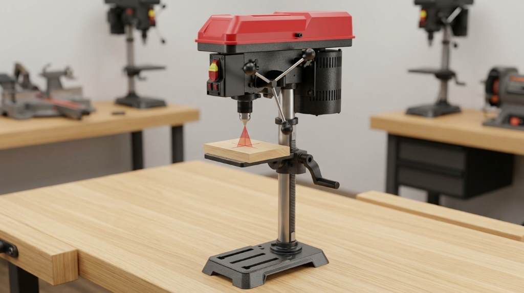
You troubleshoot this tool by inspecting belt tension, chuck runout, and laser alignment first. Next, test the quill return spring and depth stop gauge for smooth travel. If the motor hums without turning, verify electrical voltage and reset the safety switch.
Mechanical vibration and drill bit runout ruin woodworking projects during precision drilling tasks. Fortunately, the Skil DP9505-00 benchtop drill press delivers dependable accuracy through simple mechanical maintenance. In fact, workshop surveys show that eighty percent of drill press issues involve improper belt tension. Therefore, this expert guide resolves common motor stalls, wobble problems, and alignment errors quickly.
Key Takeaways
- Inspect drive belt deflection and maintain one-half inch of flex under moderate finger pressure.
- Clean the JT33 spindle taper and chuck socket thoroughly before reseating the keyed chuck.
- Calibrate the X2 crosshair laser diodes using the twin alignment screws on the casting.
- Adjust the quill return spring housing counterclockwise to eliminate loose feed handle play.
- Lock the dual depth gauge thumb nuts firmly to maintain repeatable hole drilling depths.
- Verify that the yellow magnetic safety lockout key sits firmly within the paddle switch.
Understanding Common Skil DP9505-00 Operational Symptoms
Workshop drilling demands high accuracy across diverse hardwoods, composite panels, and soft metals. However, heavy vibration and spindle chatter often compromise clean boring operations. A dull drill bit or misaligned pulley system triggers noticeable mechanical resistance immediately. Recognizing these basic warning signs prevents costly motor burnout and workpiece damage.
Furthermore, operators occasionally encounter electrical faults during regular workshop sessions. The 3.2-amp induction motor might produce an audible hum without rotating the spindle assembly. Similarly, sudden drill bit stalls can interrupt boring cycles midway through dense stock. Pinpointing the exact mechanical or electrical root cause saves substantial repair time.
Correcting Morse Taper and Keyed Chuck Runout
Diagnosing Spindle and Chuck Wobble
Drill bit wobble ruins tight woodworking joints and ovalizes clean dowel holes. First, install a straight steel rod or precision ground dowel into the chuck jaws. Tighten all three chuck key holes sequentially to distribute clamping force evenly. Then, spin the chuck slowly by hand while watching the test rod tip.
Additionally, mount a dial indicator on the steel column to measure lateral runout. Place the indicator contact point directly against the smooth chuck sleeve body. Rotate the spindle assembly carefully and note total needle movement on the dial. High runout exceeding five thousandths of an inch indicates taper contamination or poor seating.
Cleaning and Reseating the JT33 Chuck Arbor
Factory anti-rust oils attract fine sawdust inside the tapered socket over time. Consequently, tiny wood particles create microscopic gaps between the spindle and keyed chuck. Disconnect main electrical power before servicing the chuck and spindle assembly. Lower the quill completely and open the three chuck jaws into their widest position.
Next, tap a chuck removal wedge between the chuck back and the spindle shoulder. Alternatively, use a soft brass drift to break the friction taper seal safely. Clean both mating surfaces with mineral spirits and a clean microfiber cloth. Wipe away every trace of solvent and debris to ensure pristine bare metal contact.
Finally, slide the degreased chuck firmly onto the JT33 arbor by hand. Place a scrap hardwood block across the drill press cast iron table. Lower the spindle and press the open chuck forcefully against the wood block. Strike the wood block firmly with a dead blow mallet to lock the taper securely.
Adjusting 5-Speed V-Belt Tension and Drive Pulleys
Setting the Correct Belt Deflection
The Skil DP9505-00 transfers motor power using a reinforced rubber V-belt. However, improper belt tension causes either severe belt slippage or premature bearing failure. A loose belt slips under drilling pressure and stalls the chuck instantly. In contrast, excessive belt tension strains motor bearings and produces loud whining noises.
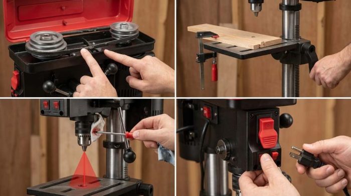
First, open the top metal pulley cover to access the drive belt assembly. Loosen the motor lock knob on the right side of the head. Pull the motor adjustment lever toward the front casting to slacken the belt. Move the belt to your desired stepped pulley grooves for proper drilling speed.
Next, push the motor backward to restore tension across the belt span. Tighten the motor lock knob firmly to secure the motor mount plate. Press your thumb against the center of the belt span between the pulleys. The belt should deflect approximately one-half inch under moderate finger pressure.
Aligning Stepped Pulley Sheaves
Misaligned pulley sheaves create aggressive belt wear and annoying vibration during high-speed operation. Specifically, the motor pulley and spindle pulley must sit along an identical horizontal plane. If either pulley slips up or down the shaft, the belt twists abnormally. This twisting motion quickly shreds rubber belt edges and reduces drilling torque.
Lay a straight metal ruler across the flat tops of both stepped pulleys. Both pulleys should align flush against the straightedge without any angular gap. If you detect misalignment, loosen the pulley setscrew using an Allen wrench. Slide the pulley vertically along the motor shaft until both surfaces match perfectly.
Skil DP9505-00 5-Speed Pulley Configuration and RPM Guide
Selecting the correct rotational speed protects cutting edges and prevents overheating during drilling. For example, large hole cutters require high torque and low spindle speeds. In contrast, small twist bits demand fast spindle rotation to clear wood shavings cleanly. The following reference table outlines factory belt positions, spindle speeds, and target materials.
| Belt Position | Spindle RPM | Motor Pulley Step | Spindle Pulley Step | Target Material | Recommended Bit Size |
|---|---|---|---|---|---|
| Step 1 (Lowest) | 570 RPM | Smallest (Bottom) | Largest (Top) | Cast iron, stainless steel, hardwood | 1 inch and larger |
| Step 2 (Low) | 900 RPM | Second from bottom | Second from top | Mild steel, brass, thick plastic | 1/2 inch to 1 inch |
| Step 3 (Medium) | 1,390 RPM | Middle step | Middle step | Dense hardwoods, aluminum sheet | 3/8 inch to 1/2 inch |
| Step 4 (High) | 2,050 RPM | Second from top | Second from bottom | Soft woods, acrylic, light resin | 3/16 inch to 3/8 inch |
| Step 5 (Highest) | 3,050 RPM | Largest (Top) | Smallest (Bottom) | Thin softwood, craft veneers | Under 3/16 inch |
Always shut off the drill press before shifting the V-belt between pulley steps. Furthermore, never force the belt across pulley ribs while the motor runs. Rotate the spindle pulley by hand to seat the belt into matching grooves gently. Proper speed selection doubles drill bit longevity and preserves motor performance over decades.
Calibrating the X2 Laser Alignment Crosshairs
Testing Crosshair Center Accuracy
The Skil X2 laser system projects two red beams that form crosshairs on your workpiece. Ideally, the laser intersection marks the exact entry point of the drill bit tip. However, shop vibration and transport bumps frequently throw factory laser diodes out of true. You must verify laser accuracy before drilling delicate finished wood parts.
Clamp a flat piece of scrap plywood firmly onto the cast iron work table. Insert a fine brad point drill bit or punch into the keyed chuck. Lower the quill to make a small prick mark in the wood surface. Raise the quill fully and turn on the laser crosshair switch.
Adjusting Horizontal and Vertical Laser Diodes
Inspect the relationship between the red laser crosshairs and your prick mark. If the beams miss the target mark, you need diode calibration. Locate the two laser adjustment set screws on the head casting sides. Each set screw controls one individual laser diode line across the table plane.
Use a small hex key to loosen the left laser diode lock screw slightly. Rotate the housing carefully until the vertical laser line bisects the center prick mark. Next, tighten the lock screw and adjust the right laser diode set screw. Align the horizontal laser line until both beams cross directly over the center point.
Calibrating the Depth Stop Gauge for Precision Drilling
Zeroing the Depth Stop Pointer
The Skil DP9505-00 features a threaded depth stop rod beside the quill collar. This mechanical gauge controls hole depth for mortises, hinge cups, and shelf pin holes. However, loose knurled stop nuts cause inconsistent drilling depths across repeated operations. Calibrating the scale indicator restores precision boring accuracy within fractions of a millimeter.
First, mount your desired drill bit securely inside the keyed chuck jaws. Lower the quill until the drill bit tip contacts your workpiece top surface. Hold the quill stationary using the feed handle with your right hand. Then, spin the knurled depth nuts upward toward the zero index mark.
Locking Repeatable Blind Hole Depths
Determine the required hole depth for your specific woodworking hardware or fasteners. Rotate the lower knurled depth nut downward along the threaded rod to your measurement. Next, spin the upper jam nut downward firmly against the lower depth nut. Locking both nuts against each other prevents vibration from shifting your depth setting.
Test the depth stop setting by boring a trial hole in scrap material. Measure the finished hole depth using a digital caliper or depth gauge ruler. If the depth varies slightly, loosen the upper jam nut and make micro-adjustments. Consistent depth stop calibration ensures clean, uniform holes across production runs.
Adjusting Quill Return Spring Tension
Relieving and Tightening the Clock Spring
A coiled clock spring returns the drill press quill upward after every drill stroke. Over time, internal spring fatigue causes the feed handle to drop or sag. Conversely, overtightening the spring creates excessive handle resistance and tires your forearm quickly. You can adjust the spring housing on the left head casting in minutes.
First, disconnect electrical power to prevent accidental motor startup during adjustment. Firmly grip the outer circular spring housing cover with your left hand. Do not release your grip, because the internal coiled spring stores significant tension. Loosen the outer lock nut with an adjustable wrench while holding the cover.
Pull the spring housing outward slightly to disengage the housing notch from the boss. Rotate the housing counterclockwise by one-quarter turn to increase upward quill return force. Alternatively, rotate the housing clockwise if the quill snaps back with aggressive speed. Slide the housing inward to seat the notch and retighten the lock nut.
Eliminating Feed Handle Backlash and Quill Play
Excessive lateral play between the quill and head casting ruins drilling precision. When you feed the quill downward, the spindle should track along a straight vertical axis. Side-to-side slop causes wandering holes and damages delicate carbide boring bits. Fortunately, the casting features a quill lock screw to eliminate unwanted play.
Extend the quill downward approximately two inches from its top resting position. Grasp the keyed chuck body and wiggle it horizontally to feel mechanical looseness. Loosen the hex lock nut on the right side of the head casting. Turn the adjustment screw clockwise slightly until you eliminate noticeable side play.
Then, check quill vertical movement by operating the three-spoke feed handle. The quill must glide downward smoothly without binding or catching along the stroke. If the quill sticks, back off the adjustment screw by one-eighth turn. Finally, tighten the outer hex lock nut securely to maintain proper quill tracking.
Resolving Motor Humming, Stalling, and Switch Failures
Checking the Removable Safety Switch Key
The Skil DP9505-00 features a prominent paddle switch with a yellow lockout key. If someone bumps the yellow key, the switch cuts electrical contacts instantly. The motor will not receive current even when you flip the main toggle paddle. Therefore, check the safety lockout key before investigating complex electrical problems.
Pull out the yellow plastic key and inspect the locking prongs for cracks. Clean accumulated wood dust out of the female switch cavity using compressed air. Firmly press the key back into the center slot until it clicks. Flip the paddle switch upward to verify normal motor startup.
Inspecting Motor Capacitors and Circuit Voltage
An induction motor that hums loudly without spinning usually indicates insufficient starting voltage. First, verify that your wall receptacle provides a full 120 volts of alternating current. Connecting the drill press through thin, lightweight extension cords causes severe voltage drops. Always plug the machine directly into a wall receptacle or heavy 12-gauge cord.
Furthermore, inspect the motor start capacitor inside the metal motor housing bulge. A defective start capacitor prevents the motor from generating sufficient rotational starting torque. If the capacitor bulges or leaks oil, replace it with an identical microfarad unit. Testing the capacitor with a digital multimeter confirms electrical capacitance within factory specifications.
Preventive Maintenance Checklist for Benchtop Longevity
Regular maintenance preserves smooth mechanical movement and prevents premature component failure. For example, microscopic sawdust absorbs moisture and accelerates corrosion across bare cast iron surfaces. Apply a thin coat of paste wax to the work table and base monthly. Buff the wax dry to create a slick, rust-resistant protective barrier.
Additionally, lubricate the steel column and rack gear using dry silicone spray. Wet petroleum oils attract airborne wood dust and form sticky, abrasive grime deposits. Wipe the steel column clean before spraying a fresh protective film of lubricant. Raise and lower the cast iron table assembly to distribute lubricant across teeth.
Finally, inspect the V-belt monthly for glazing, cracks, or frayed rubber strands. Replace any damaged belt immediately to prevent sudden snapping during heavy drilling tasks. Clean the stepped pulley grooves using a stiff nylon brush to remove rubber dust. A clean drive system delivers smooth, vibration-free drilling power year after year.
Conclusion: Restore Peak Drilling Precision
Mastering simple mechanical adjustments keeps your benchtop drill press running smoothly for years. Systematic inspection of belt tension, chuck seating, and laser crosshairs eliminates common drilling flaws. Furthermore, calibrating depth stops and quill return springs guarantees repeatable woodworking precision every time. You can solve most operational issues quickly with basic workshop hand tools.
Do not let chuck runout or belt slippage spoil your next fine woodworking project. Inspect your drive pulleys, calibrate the laser alignment, and start drilling clean holes today!
Frequently Asked Questions
Why does my Skil DP9505-00 drill press hum but not spin?
A slipped drive belt, jammed spindle, or missing safety switch key prevents motor rotation.
How do I reduce chuck wobble on this benchtop drill press?
Clean the JT33 arbor taper and firmly seat the chuck using a wooden mallet.
How tight should the V-belt be on the Skil DP9505-00?
Maintain approximately one-half inch of belt deflection under light thumb pressure between the pulleys.
Why does my drill press quill not return to the top?
Wind the outer spring housing counterclockwise by one turn to increase upward return tension.
How do I align the X2 laser crosshairs on workpiece marks?
Adjust the two laser diode set screws on the head until the beams intersect cleanly.